


Whether you are at home, on the road, or at the office, it is inevitable that a motor will be used one or more times during your day. The first motor was invented in 1891 by Michael Faraday and operated based on the principles of EMF or (Electrical Magnetic Field). Throughout this article, I will share Michael Faraday’s Law of Induction, the different types of motors, and how they work.
According to Merriam-Webster, a motor is defined by, and I quote, “1) one that imparts motion, 2) any of various power units that develop energy or impart motion: such as a: a small compact engine b: Internal Combustion Engine c: a rotating machine that transforms electrical energy into mechanical energy. Before understanding how a motor works, it’s vital to understand Michael Faraday’s Principle Law of Induction. Michael’s Law of Induction states that any circuit which carries a current also has a magnetic field and how that field will interact to produce a force called electromotive force.
Specifically, the law states that the rate of change or magnetic flux through a coil about the magnitude of the electro-motive force induced in the coil is E= dΦ?/dt. Note that EMF force refers to the potential of the loaded coil. As a result of the applied electromagnetic induction, we know which direction the current is flowing based on Heinrich Lenz in his Lenz Law, established in 1833. His law states that the direction will always oppose the change in flux that created it. Thus any magnetic induction field will always be in the opposite direction of the current. Thus Formula may be incorporated into Faraday’s by changing the = sign in the equation to a minus as such E- dΦ?/dt. Since there are usually multiple coils with induction, the N variable is added to represent the number of turns or coils as represented as E-NdΦ?/dt, and the Greek symbol indicates change.
To illustrate this, picture a wire with current running through it; thus, an electron can move within the connected wire to form a loop. Remember that the magnetic field is always perpendicular to the current flowing and will be released as heat in resistance to the wire. Thanks to these discoveries, motors, transformers, and generators are possible.
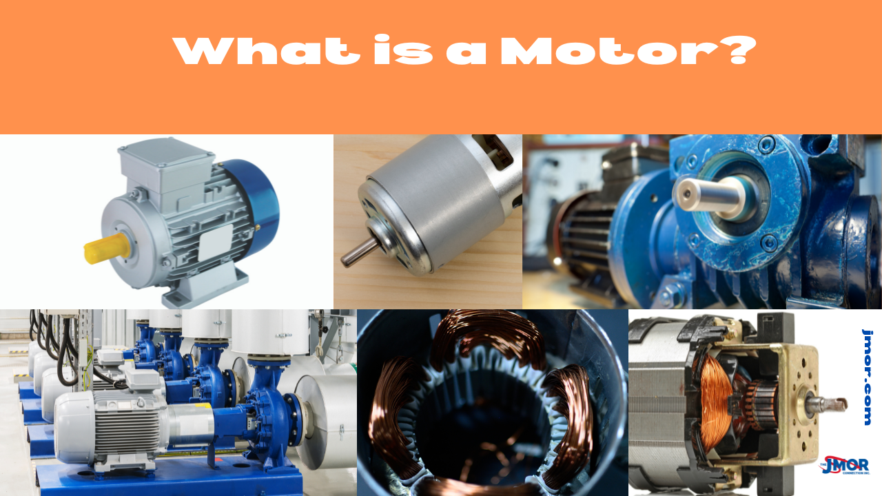
A simple Motor contains six parts: a stator, rotor, commutator, brushes, axle, and a DC power supply. Outside a DC motor is the stator, a permanent magnet that does not move. The inside part of an electromagnetic motor system is called a rotor or a flywheel. When a toque is applied, the flywheel rotates inside a magnetic field and is made of t-shape laminated disks. Important to note that wrapped around these t-share arms are coil windings that carry the current from the battery. The commutator is a pair of plates attached to the axle and provides two connections for the coil of the electromagnet. There also are brushes comprising two pieces of metal or carbon that make contact with the contacts of the commutator.
Suppose the positive battery connection is wired to the positive terminal on the motor and the negative terminal to the negative terminal on the motor. In that case, the motor will move in a counterclockwise direction. However, if we reverse the terminal wiring so the positive battery connection is wired to the negative connection on the motor and the negative battery connection is wired to the positive, the motor will spin in the opposite direction, which is clockwise. Did you know that there are several different types of DC Motors available?
DC Motors come in permanent magnet DC motors, series DC Motors, Shunt DC Motors, and compound DC Motors, but what is the difference? A permanent DC Magnet Motor operates by a permanent magnet, creating the magnetic field or magnetic flux. This type of motor does not have windings on the stator frame. DC permanent magnet motors use permanent magnets to create a magnetic field for which the rotor will be responsible for generating torque. These motors have tremendous starting torque and flexibility for excellent speed. Regulation.
Series DC Motors, or series wound DC Motors, is when the entire armature current flows through the windings. DC Motors have a large amount of starting torque. However, they are unable to regulate speeds. Did you know these motors are often damaged easily because many people run them without loads?
Another type of motor is called a Shunt DC Motor, in which the winding is only parallel to the armature wiring and not the series winding. Shunt Motors provide excellent speed control since the shunt can be activated separately from the armature windings. Shunt DC Motors can be easily reversed by activating a single control.
Compound Motors or compound wound motors have both a series and shunt winding. They have a good starting torque but cannot regulate speed. Compound Motors can be connected in two—configurations: cumulatively and differential. The cumulative option connects the series field to aid the shunt field with high starting torque with less speed reduction control. The motor has flexible speed control when utilizing the differential configuration and usually operates at a set speed.
Thus, without Michael Faraday, we would have had the convenience of motors. That means we have no automatic garage door opener, dishwasher, appliances, cars, boats, or other daily luxury devices. The next time you start a motor, take a moment to be grateful for Michael Faraday and Heinrich Lenz for their contributions that made our society a better place to live. Remember, a motor is a device that converts electrical energy into mechanical energy.